Achieving High Availability Across the OSI Layers: A Complete Guide
High availability is a critical requirement for modern networks—it ensures your systems stay operational even when individual components fail. But achieving true high availability isn’t just about redundant hardware or backup servers. It requires a comprehensive approach that addresses resilience at every layer of the network stack.
In this guide, we’ll explore how to implement high availability strategies across all seven layers of the OSI model, from the physical cables and switches at the foundation to the applications and databases at the top. We’ll also examine how these layers work together to create a truly resilient architecture.
Layer 1: Physical Layer — Building a Solid Foundation
The Physical Layer forms the foundation of your network infrastructure. This layer encompasses all the tangible hardware components: cables, fiber optics, and physical networking devices. Without redundancy at this layer, no amount of software-based failover can keep your network running.
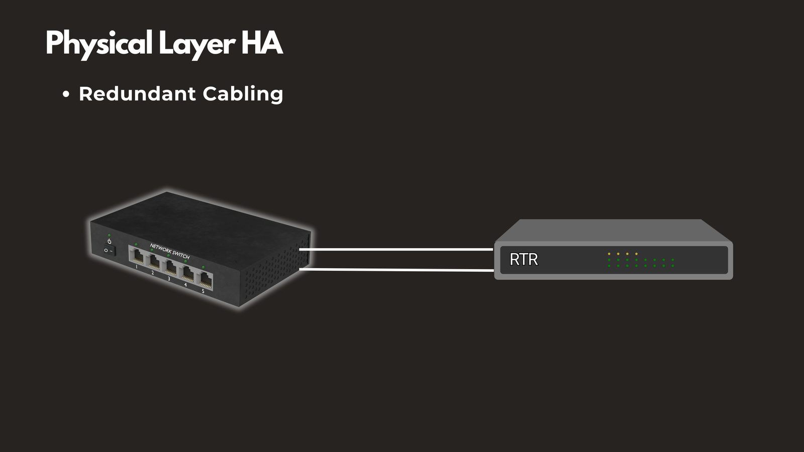
Redundant Cabling
Deploy multiple physical cables between critical network devices. If one cable is cut or damaged during maintenance or an accident, traffic automatically flows through the alternate path. This simple measure can prevent complete network outages caused by a single cable failure.
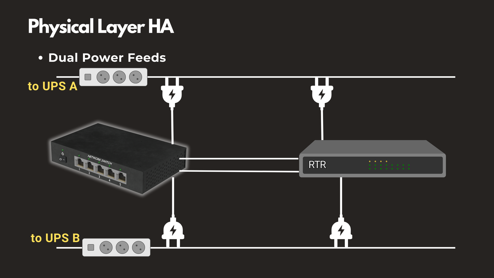
Dual Power Feeds
Connect critical devices to two separate power sources or UPS systems. Power failures are among the most common causes of downtime. When one power circuit fails, the secondary power feed keeps your equipment running without interruption.
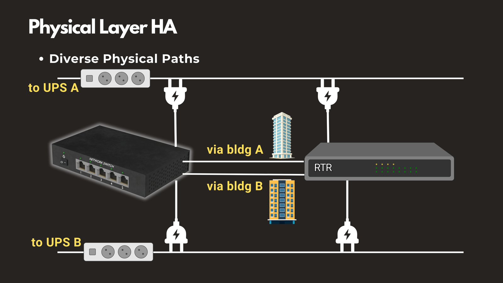
Diverse Physical Paths
Route cables through different conduits or building pathways. A construction accident that severs one fiber line won’t take down your entire network if you have cables running through separate physical routes. This is especially important for connections between buildings or data centers.
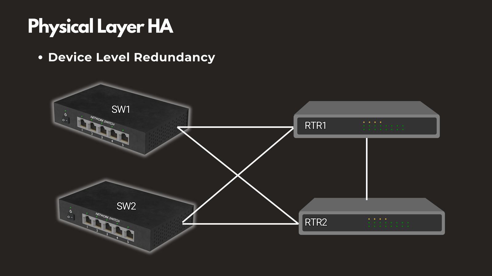
Device Level Redundancy
Deploy backup hardware for critical network devices. Having spare switches, routers, and other equipment ready for immediate deployment minimizes downtime when hardware failures occur.
The Physical Layer is your foundation. If it fails without backup systems in place, none of the higher-layer redundancy mechanisms matter—you simply won’t have the physical infrastructure to run your services.
Layer 2: Data Link Layer — Ensuring Local Network Resilience
The Data Link Layer, primarily managed by switches, handles communication within local network segments using MAC addresses. Layer 2 high availability strategies ensure your local networks remain connected even when individual switch ports or devices fail.
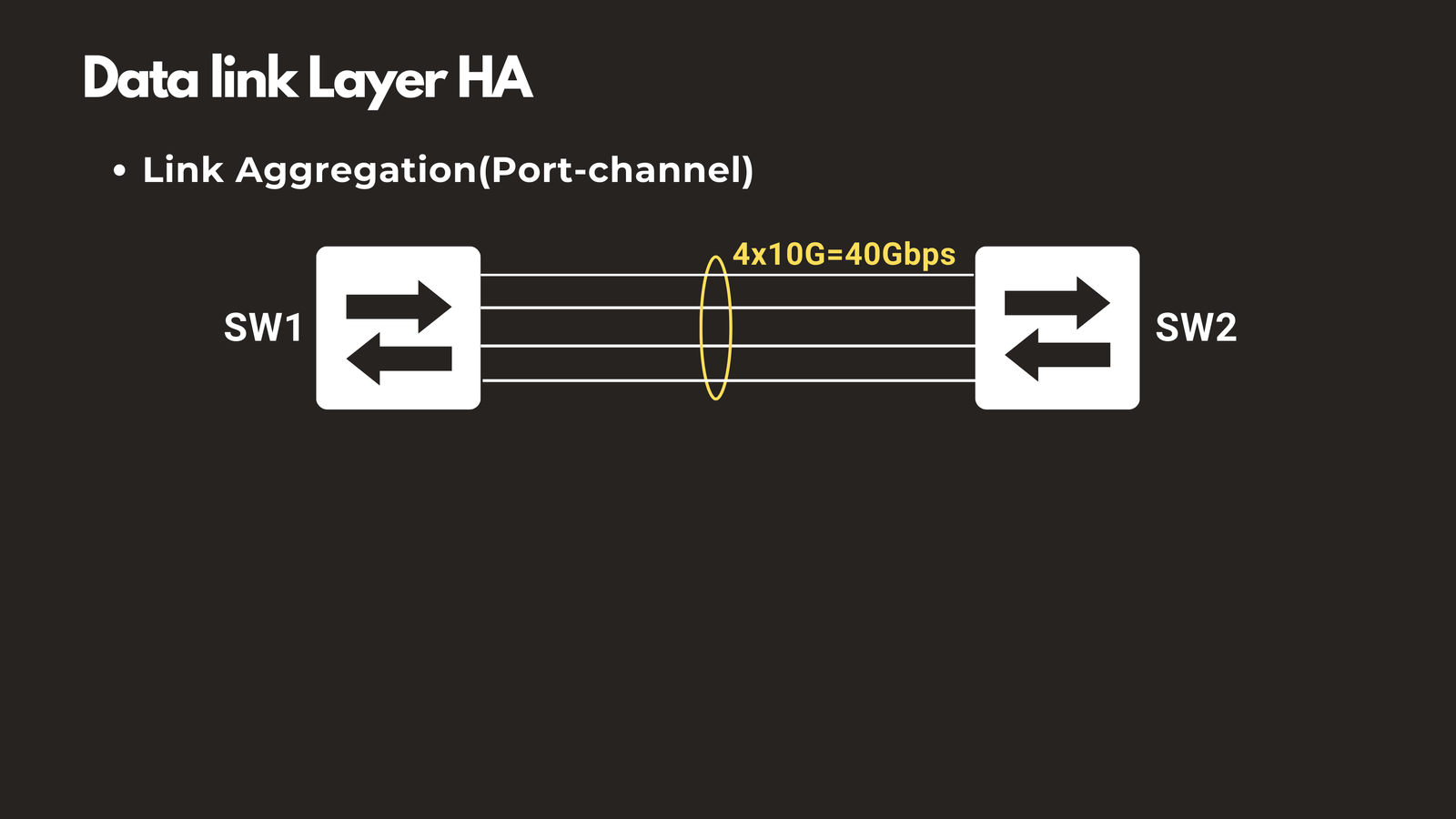
Link Aggregation (LACP)
Link Aggregation Control Protocol allows you to bundle multiple physical switch ports into a single logical connection. For example, combining four 10 Gbps links creates one 40 Gbps logical link. If one physical port fails, the remaining ports continue operating seamlessly, maintaining both connectivity and a portion of the total bandwidth.
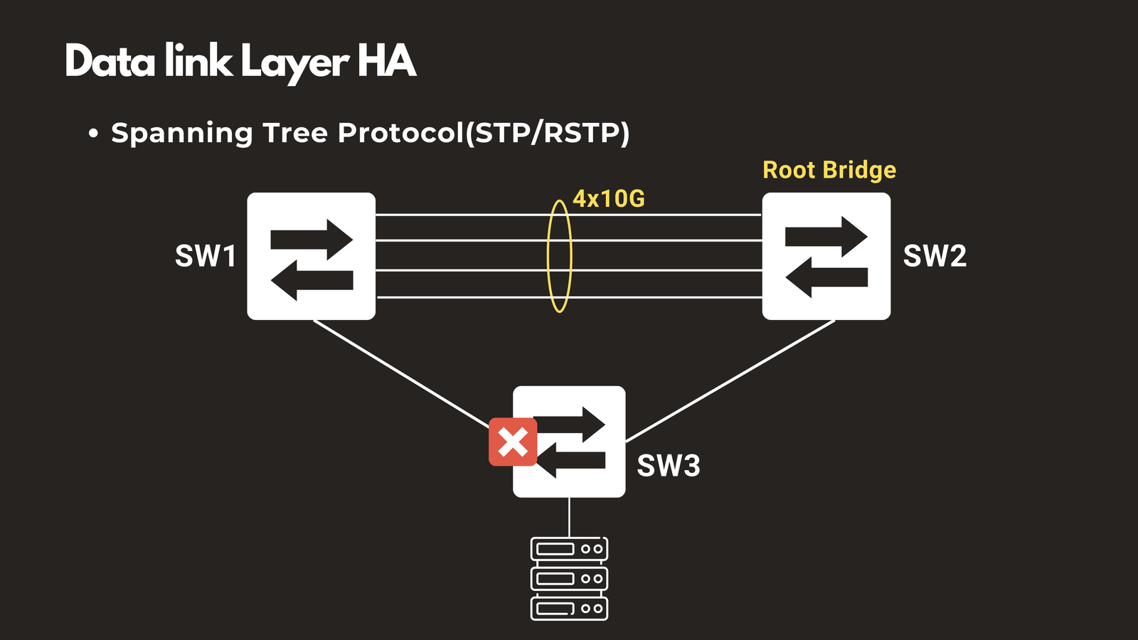
Spanning Tree Protocol (STP/RSTP)
STP prevents switching loops while maintaining backup paths in your network topology. When your primary link fails, STP activates the redundant path to restore connectivity. Modern implementations like Rapid Spanning Tree Protocol (RSTP) can complete this failover in less than 10 seconds, minimizing disruption.
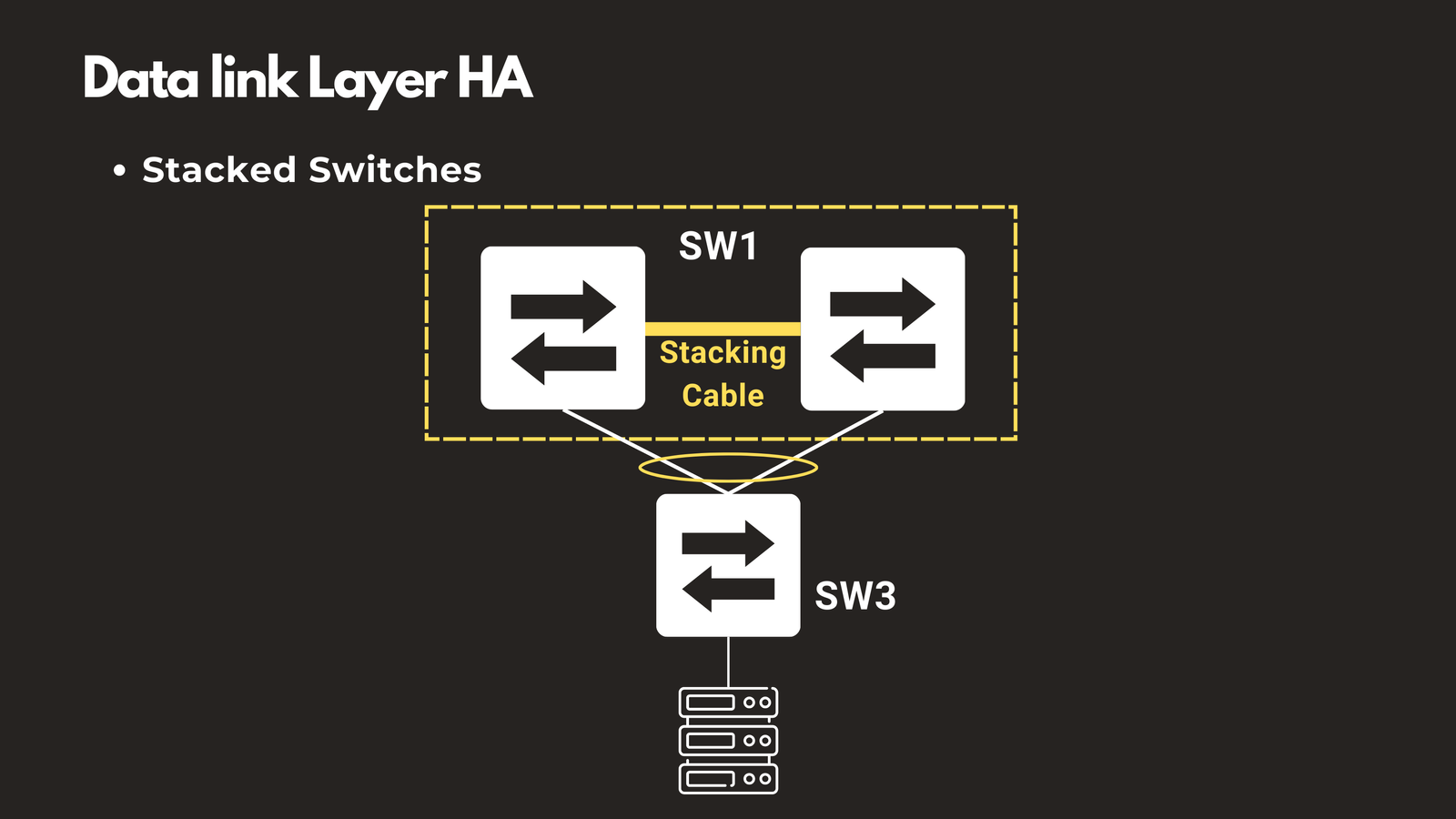
Stacked Switches
Switch stacking technologies, such as Cisco StackWise, allow multiple physical switches to function as a single logical unit. If one switch in the stack fails, the remaining switches continue operating, providing seamless failover without manual intervention.
Layer 2 high availability ensures your local network segments maintain connectivity during hardware failures, creating a resilient foundation for the higher layers.
Layer 3: Network Layer — Intelligent Routing and Failover
The Network Layer is where routing decisions are made, and it’s where high availability becomes particularly powerful. Layer 3 protocols can automatically detect failures and reroute traffic through alternate paths with minimal disruption.
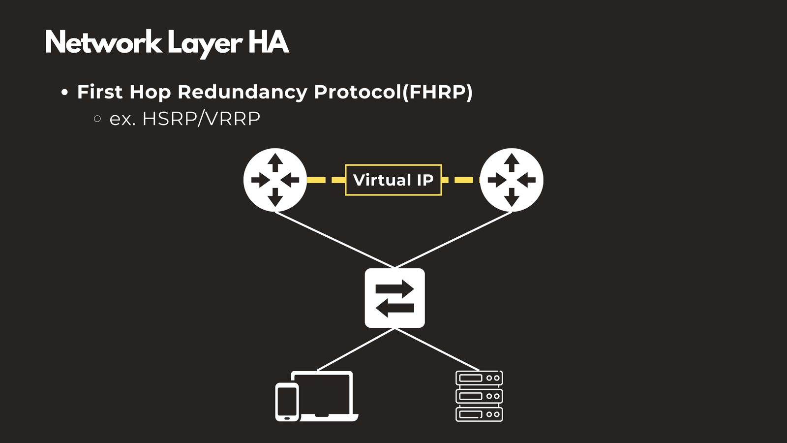
First Hop Redundancy Protocols (HSRP/VRRP)
Protocols like Hot Standby Router Protocol (HSRP) and Virtual Router Redundancy Protocol (VRRP) allow two or more routers to share a virtual IP address as the default gateway. End devices point to this virtual IP, and if the primary router fails, the backup router takes over instantly. Users experience no interruption because they continue using the same gateway IP address.
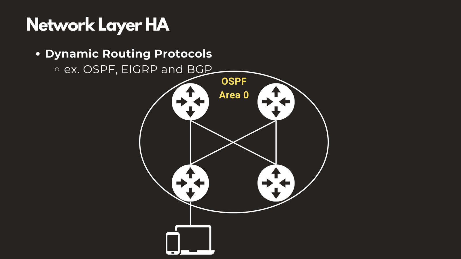
Dynamic Routing Protocols (OSPF, EIGRP, BGP)
Dynamic routing protocols automatically discover and maintain multiple paths through your network. Open Shortest Path First (OSPF), Enhanced Interior Gateway Routing Protocol (EIGRP), and Border Gateway Protocol (BGP) continuously monitor network conditions. When the primary route fails, these protocols converge in milliseconds, automatically switching traffic to backup routes.
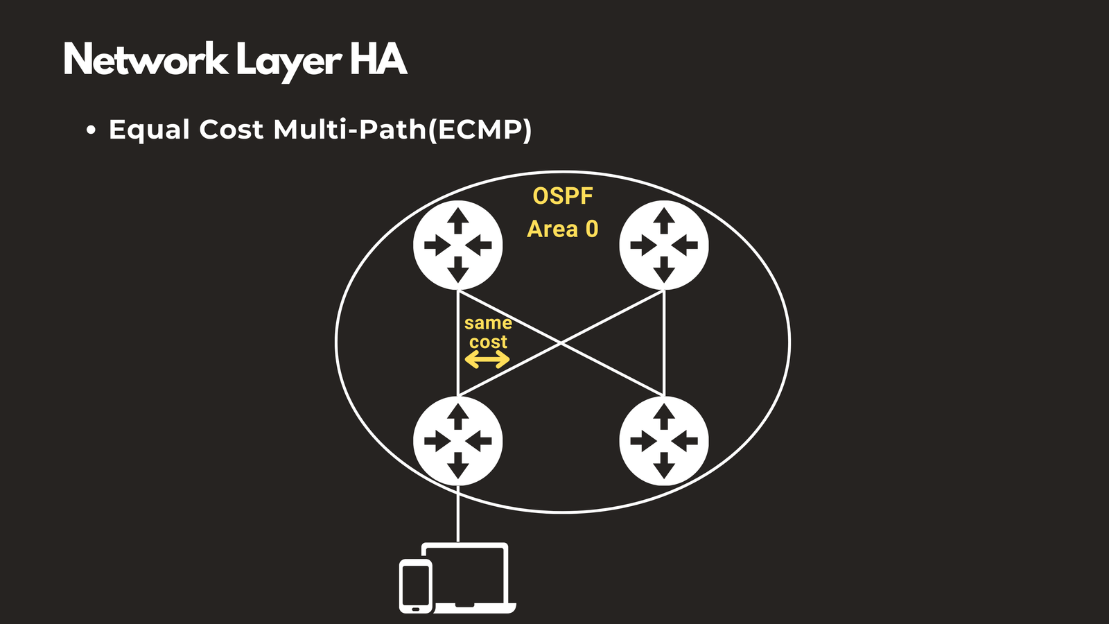
Equal Cost Multi-Path (ECMP)
When dynamic routing protocols detect multiple paths with equal cost, ECMP allows traffic to be load-balanced across all available paths simultaneously. Rather than keeping backup routes idle, ECMP provides both improved performance through load distribution and redundancy. If one path fails, traffic continues flowing through the remaining paths.
Layer 4: Transport Layer — Connection Management and Distribution
The Transport Layer, which handles TCP and UDP connections, is where load balancers operate to distribute traffic and ensure session continuity.
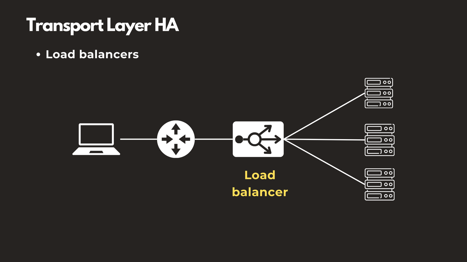
Load Balancers
Load balancers distribute incoming connections across multiple backend servers. They continuously monitor server health through periodic health checks. When a server crashes or becomes unresponsive, the load balancer immediately stops sending new traffic to it and redirects users to healthy servers automatically.
Modern load balancers provide several critical capabilities:
- Session Persistence: Maintains user session state by ensuring requests from the same client are directed to the same backend server
- Connection Multiplexing: Reduces the number of connections to backend servers, optimizing resource usage and providing a buffer before server failures impact users
Layer 4 high availability ensures individual connections survive even when backend infrastructure changes, providing a seamless experience for end users.
Layers 5-7: Session, Presentation & Application — Application-Level Resilience
The upper layers of the OSI model are where your actual applications, databases, and services operate. High availability at these layers ensures your business-critical applications remain accessible regardless of infrastructure failures.
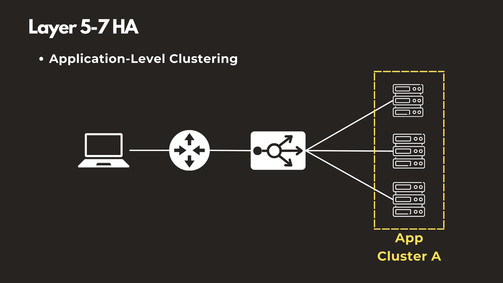
Application-Level Clustering
Deploy database servers, web servers, and application servers in clustered configurations. When one node fails, the remaining nodes in the cluster continue handling requests. Modern orchestration platforms like Kubernetes automatically detect failed containers, restart them, and redistribute workloads across healthy nodes—all without human intervention.
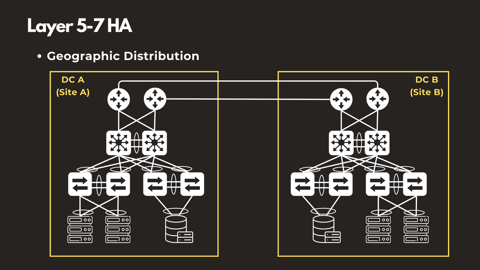
Geographic Distribution
Distribute applications across multiple data centers or geographic regions. Companies like Amazon, Netflix, and Google run services in dozens of locations worldwide. When a regional outage occurs—whether due to natural disasters, power failures, or network issues—users are automatically served from another location with minimal service disruption.
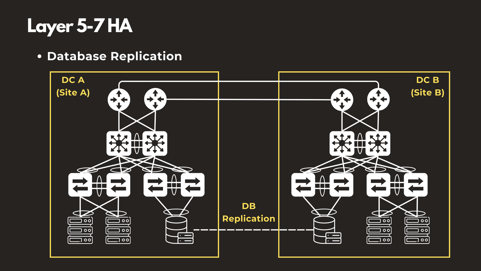
Database Replication
Implement master-slave or multi-master database replication to ensure data is continuously synchronized across multiple database servers. When your primary database crashes, you can failover to a replica with minimal downtime and no data loss. This protects against both hardware failures and data corruption scenarios.
Bringing It All Together: A Holistic Approach to High Availability
True high availability requires a comprehensive, stack-wide strategy. Implementing redundancy at just one or two layers leaves your infrastructure vulnerable to single points of failure. A resilient architecture addresses every layer:
- Layer 1: Redundant physical infrastructure including cabling, power, and diverse paths
- Layer 2: Link aggregation, spanning tree protocols, and switch stacking
- Layer 3: Redundant gateways with FHRP and dynamic routing protocols
- Layer 4: Load balancing with health checks and session management
- Layers 5-7: Clustered applications, geographic distribution, and database replication
Each layer builds upon the one below it, creating a defense-in-depth strategy for availability. A failure at any single layer can be compensated for by redundancy at that layer, preventing cascading failures that would otherwise bring down your entire system.
Consider a practical example: If you have perfectly configured application clustering and database replication (Layers 5-7), but your network uses a single physical cable with no backup (Layer 1), one accidental cable cut will bring down your entire infrastructure. Conversely, having redundant physical infrastructure won’t help if your application can’t failover to a backup server.
Conclusion
Building highly available systems requires careful planning and implementation across all layers of the OSI model. By understanding how each layer contributes to overall resilience and implementing appropriate redundancy mechanisms at each level, you can create network architectures that withstand component failures and continue serving users with minimal disruption.
Remember that high availability is not just about technology—it’s about designing systems with failure in mind. Every component will eventually fail, the question is whether your architecture can gracefully handle those failures without impacting your users.
Have questions about High Availability Across the OSI Layers? Check out the video on this link https://youtu.be/u-8HblkofHY, drop a comment and let’s discuss!