Understanding Spanning Tree Protocol: Root Bridge Election and Port Blocking
Network redundancy is essential for maintaining uptime, but it introduces a critical challenge: broadcast storms. When devices send broadcast frames to discover destinations in a local network, a simple topology with one switch handles this efficiently. However, as networks grow and additional switches are added for redundancy, these broadcast frames can circulate endlessly, creating loops that can bring down your entire network.
This is where Spanning Tree Protocol (STP) becomes indispensable. STP prevents Layer 2 loops by strategically disabling specific ports and dynamically enabling them when the topology changes. In this guide, we’ll explore the two core operations that make STP work: root bridge election and the process of identifying which ports to block.
What Is a Root Bridge?
Just as trees grow from their roots, spanning tree topologies are built from a central reference point called the root bridge. The root bridge serves as the authoritative center of the network, acting as the reference point for all path calculations that eliminate Layer 2 loops.
How the Root Bridge Is Elected
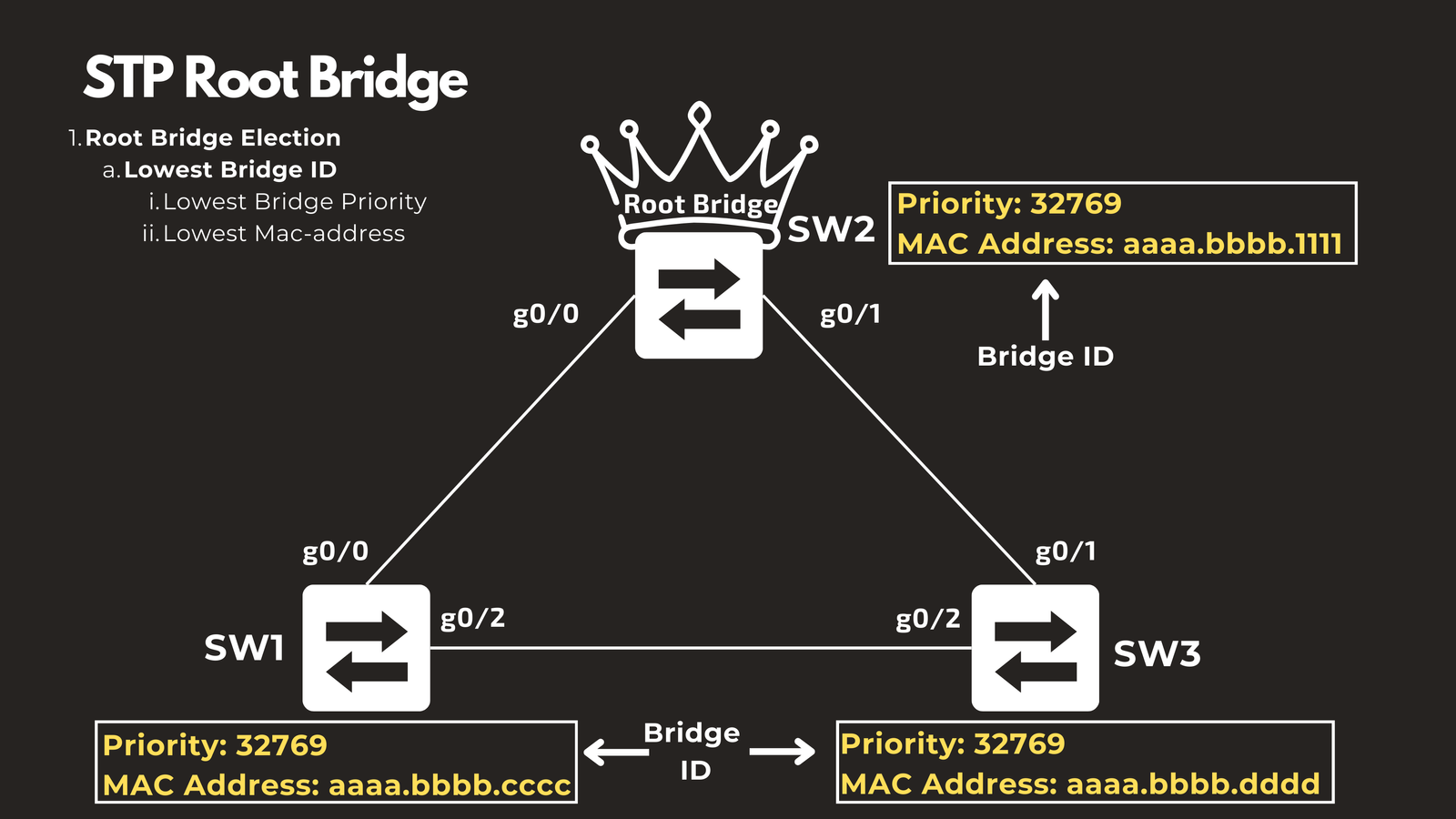
The root bridge is elected based on the Bridge ID of each switch in the topology. The fundamental rule is simple: the switch with the lowest Bridge ID becomes the root bridge.
The Bridge ID consists of two components:
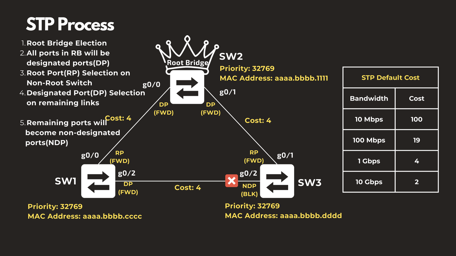
- Bridge Priority: A configurable value that defaults to 32768 plus the VLAN ID. For VLAN 1, this results in a default bridge priority of 32769.
- MAC Address: A unique hardware address burned into the switch during manufacturing.
These values are exchanged between switches using Bridge Protocol Data Units (BPDUs) when switches join the topology. The election process follows a clear hierarchy:
- First: The switch with the lowest bridge priority wins
- Tiebreaker: If bridge priorities are equal, the switch with the lowest MAC address becomes the root bridge
Example Scenario
Consider a topology with three switches, all configured with the same default bridge priority of 32769. In this case, the MAC addresses become the deciding factor. If Switch 2 has the lowest MAC address among all switches, it will be elected as the root bridge, regardless of its position in the physical topology.
The STP Port Selection Process
Once the root bridge is elected, STP follows a systematic process to determine which ports should forward traffic and which should be blocked to prevent loops. This process ensures a loop-free topology while maintaining connectivity to all network segments.
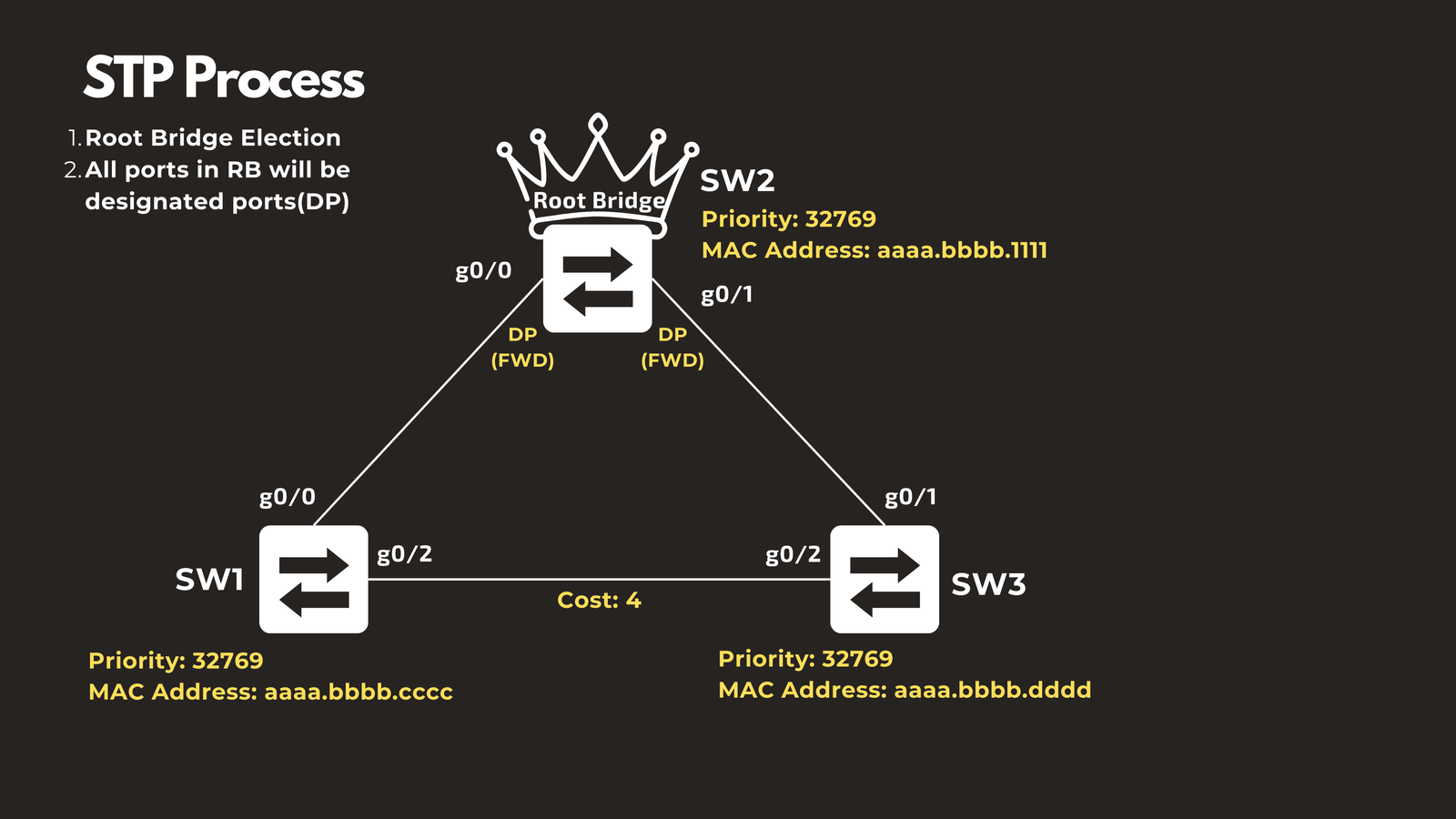
Step 2: Root Bridge Ports Enter Forwarding State
All ports on the root bridge are automatically designated as designated ports and placed in a forwarding state. Since the root bridge is the reference point for the entire topology, its ports never need to be blocked—they form the foundation of the spanning tree.
Step 3: Non-Root Switches Select Their Root Port
Each non-root switch must select exactly one root port—the port that provides the best path back to the root bridge. The selection follows a priority-based decision tree:
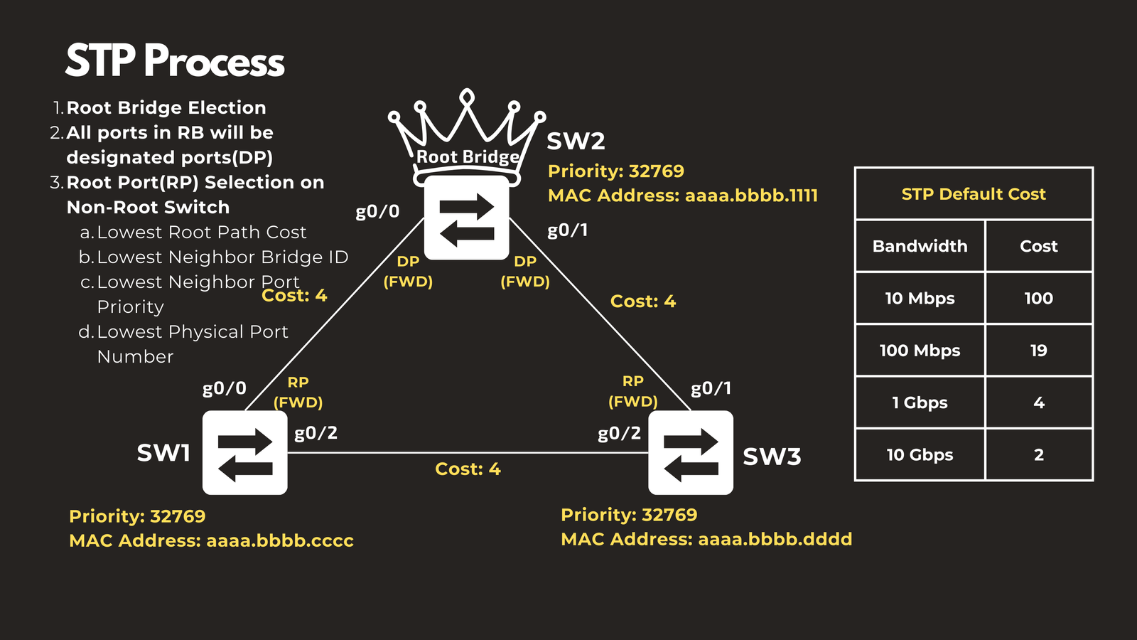
Primary Criterion: Lowest Root Path Cost
The root path cost is the cumulative cost of all links from a switch back to the root bridge. Costs are assigned based on the bandwidth of each port, with higher-speed links receiving lower costs:
- 10 Gbps: Cost of 2
- 1 Gbps: Cost of 4
- 100 Mbps: Cost of 19
- 10 Mbps: Cost of 100
Ports directly connected to the root bridge naturally have the lowest costs and are typically selected as root ports.
Tiebreaker 1: Lowest Neighbor Bridge ID
If multiple ports have equal root path costs, the switch examines which neighboring switch each port connects to. The port connected to the neighbor with the lowest Bridge ID is selected as the root port.
Tiebreaker 2: Lowest Neighbor Port Priority
When multiple ports connect to the same neighboring switch (which would have the same Bridge ID), the decision is based on the port priority of the neighbor’s ports. The local port connected to the neighbor port with the lowest priority becomes the root port.
Final Tiebreaker: Lowest Physical Port Number
If all other factors are equal, the port with the lowest physical port number (e.g., Gi0/1 over Gi0/2) is selected as the root port.
Step 4: Selecting Designated Ports for Each Link
After root ports are identified, the remaining links in the topology must each have exactly one designated port—the port that will forward traffic on that particular network segment. The other end of the link will be blocked.
Consider a link between Switch 1 and Switch 3. Both ends of this link need to determine which side will be the designated port. The selection process follows this order:
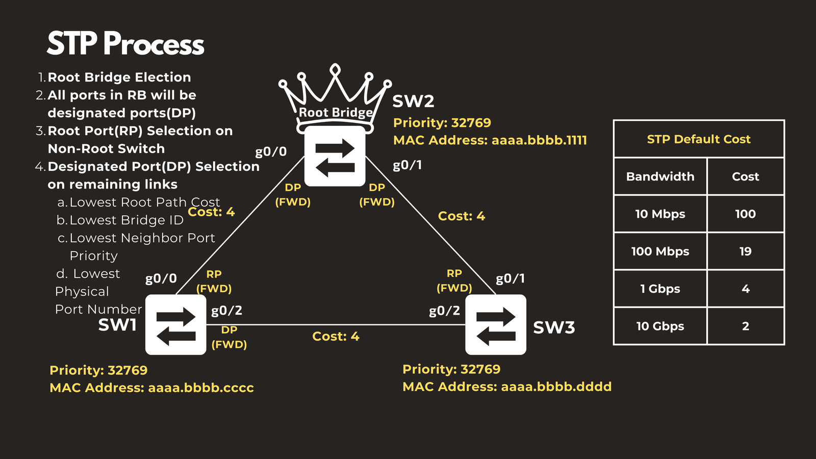
Primary Criterion: Lowest Root Path Cost
The port with the lower cumulative cost to reach the root bridge becomes the designated port. This ensures traffic takes the most efficient path.
Tiebreaker 1: Lowest Bridge ID
If both ports have equal root path costs (as is often the case for ports on the same link), the port belonging to the switch with the lower Bridge ID becomes the designated port.
For example, if both Switch 1 and Switch 3 have ports with equal root path costs, but Switch 1 has a lower Bridge ID, then Switch 1’s port (such as Gi0/2) becomes the designated port.
Tiebreaker 2: Lowest Port Priority
When multiple ports on the same switch compete for designated port status, the port with the lowest port priority wins.
Final Tiebreaker: Lowest Physical Port Number
If all other factors are tied, the port with the lowest physical port number is selected.
Step 5: Remaining Ports Enter Blocking State
All ports that are neither root ports nor designated ports become non-designated ports and enter a blocking state. These blocked ports do not forward traffic under normal circumstances, but they remain ready to activate if the topology changes due to a link or device failure.
How STP Maintains a Loop-Free Topology
The systematic election and port selection process ensures that:
- There is exactly one root bridge serving as the network’s reference point
- Each non-root switch has exactly one path back to the root bridge (via its root port)
- Each network segment has exactly one designated port forwarding traffic
- All redundant paths are blocked to prevent loops
This creates a logical tree structure—hence the name “spanning tree”—where traffic can reach any destination without circulating in loops.
Dynamic Adaptation to Topology Changes
One of STP’s critical features is its ability to respond to network changes. When a link fails or a switch goes offline, STP recalculates the topology and can unblock previously blocked ports to maintain connectivity. Similarly, when new devices are added to the network, STP incorporates them into the spanning tree while maintaining loop-free operation.
Practical Considerations
While STP is essential for preventing loops in redundant Layer 2 networks, it does leave some bandwidth unused by design—blocked ports don’t forward traffic under normal circumstances. Modern networks often combine STP with technologies like Link Aggregation (Port-Channel/LACP) to utilize multiple physical links while maintaining loop prevention. Port-Channel bundles multiple links into a single logical connection, allowing all physical links to forward traffic simultaneously while STP treats the bundle as a single link.
Conclusion
Spanning Tree Protocol is a foundational technology that makes redundant Layer 2 networks possible. By systematically electing a root bridge and determining which ports should forward or block traffic, STP eliminates the dangerous loops that would otherwise cripple network performance. Understanding how root bridge election and port blocking work gives network engineers the knowledge to design resilient networks, troubleshoot connectivity issues, and optimize network topologies for both reliability and performance.
The beauty of STP lies in its automatic operation—once configured, it continuously monitors the network and adapts to changes without manual intervention, ensuring your network remains both redundant and loop-free.
Have questions about Spanning-Tree Protocol Root Bridge Election and Blocking Ports? Check out the video on this link https://youtu.be/0bMOSaX4pvA, drop a comment and let’s discuss!