 Packetbrew
Network Architectures That You Need to Know
Your home Wi-Fi, your company’s office network, and the data centers behind services like Netflix all run on the same handful of proven architectural patterns. Get the architecture wrong, and you end up with bottlenecks and outages. Get it right, and the network just works.
In this post, we’ll walk through the architectures every network engineer should be able to recognize and explain.
Here’s what we’ll cover:
- Legacy topologies (bus and star)
- Three-tier hierarchical design
- Collapsed core
- Spine-leaf
- Cloud network architecture
- WAN design: hub-and-spoke and mesh
Legacy Topologies: Bus and Star
Every modern design traces back to two foundational topologies.
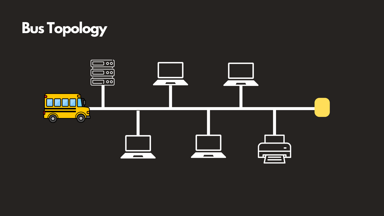
Bus topology is the simplest: one shared cable, and every device taps directly into it. It’s cheap and easy to wire up, but it has an obvious flaw — a single break anywhere on that cable takes down the entire segment, and every device on it competes for the same bandwidth. You won’t find bus topology in production networks anymore; it mostly survives in networking textbooks and legacy industrial control systems.
Star topology solved bus topology’s biggest weakness. Instead of one shared cable, every device connects individually to a central switch. If one cable fails, only that one device drops off the network — everything else keeps running.
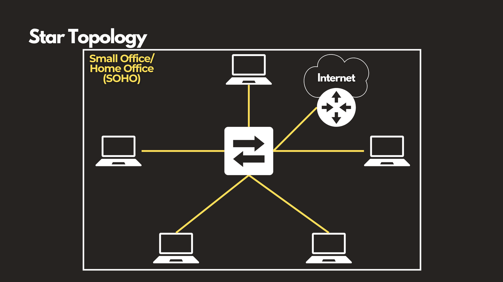
This is what a small office or home office (SOHO) network looks like today: a router or switch at the center, with everything else — laptops, phones, printers, smart devices — connecting back to it. It’s also the pattern used at the access layer of much larger enterprise networks.
The tradeoff is that the central switch is now a single point of failure. If it goes down, the whole star goes down with it. That single limitation is exactly the problem the next architecture was designed to solve.
Three-Tier Hierarchical Design
Most enterprise campus networks — corporate headquarters, universities, hospitals — are still built on three-tier hierarchical design. It organizes the network into three distinct layers, each with its own job.
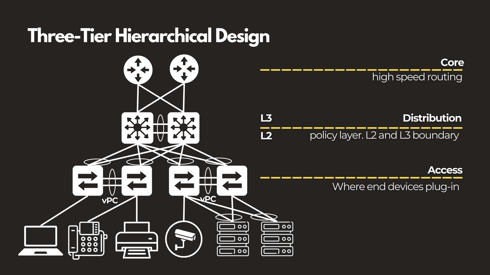
Access layer. This is where end devices physically connect: laptops, phones, printers, cameras, servers. Access switches handle port security, VLAN assignment, and Power over Ethernet for devices like phones and wireless access points.
Distribution layer. This is the policy layer. It aggregates traffic coming up from multiple access switches and enforces routing between VLANs, access control lists, and quality of service rules. It’s typically where Layer 2 switching ends and Layer 3 routing begins.
Core layer. The core has one job: move traffic between distribution blocks as fast as possible. It deliberately avoids policy enforcement, because the busiest part of the network shouldn’t be slowed down doing extra work.
The design principle holding all three layers together is redundancy — dual uplinks and dual switches at every layer, so a single link or device failure never takes the whole network down. Protocols like Spanning Tree, or more modern approaches like virtual port channels, let those redundant links exist without creating loops.
Three-tier design makes sense anywhere you have hundreds to thousands of endpoints spread across multiple buildings or wiring closets — think a corporate headquarters, a university campus, or a hospital network.
Collapsed Core
Not every site is large enough to justify three full layers. For a smaller campus or a branch office, running separate distribution and core switches is often more infrastructure than the traffic actually needs.
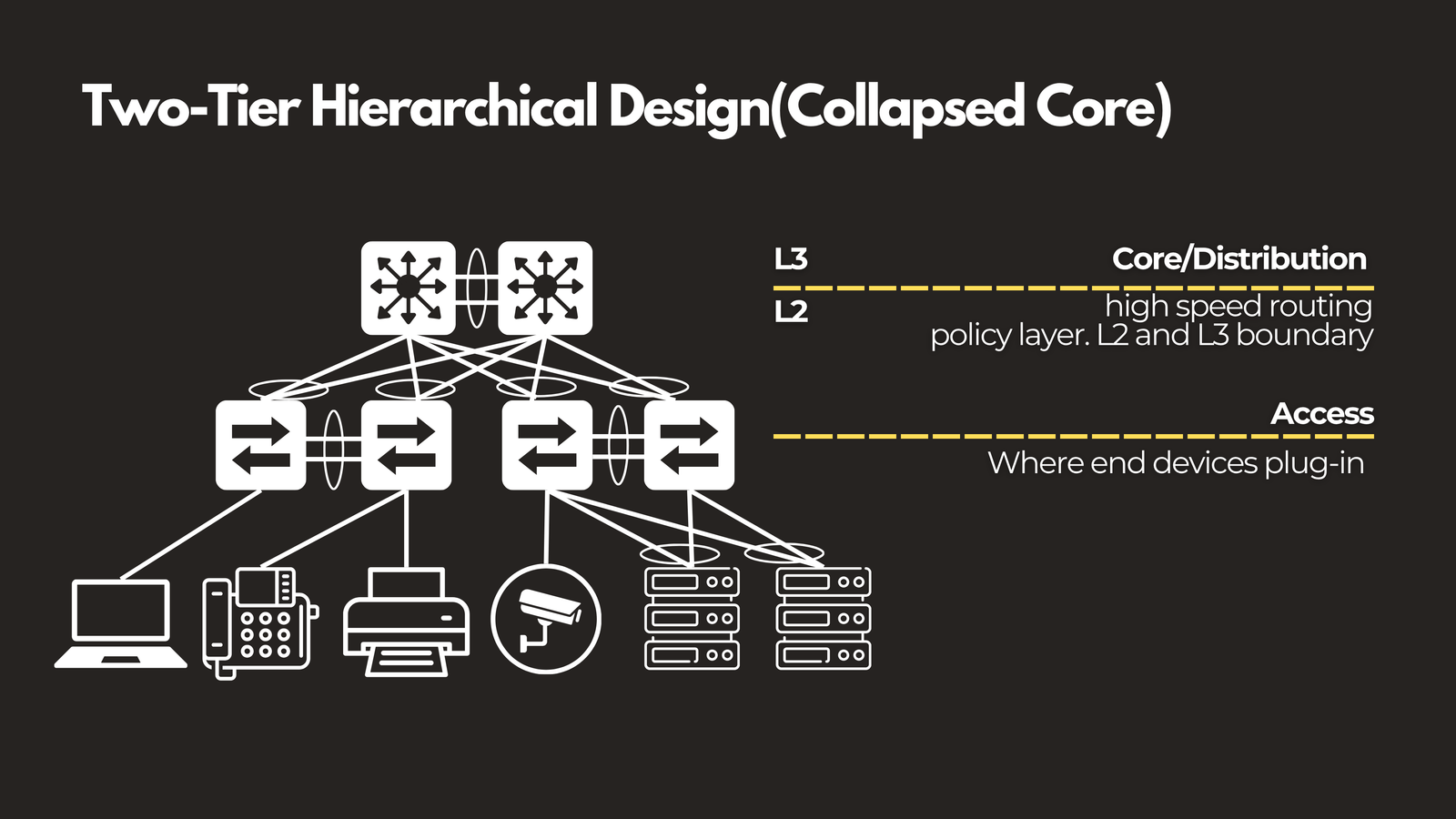
Collapsed core merges the distribution and core layers into a single pair of switches. Access switches connect directly into that pair, which handles both routing and high-speed forwarding at once.
It’s simpler to manage and cheaper to build than a full three-tier design. The tradeoff is that the core pair is now doing double duty, so redundancy at that layer matters even more than usual — if that pair goes down, there’s no separate distribution layer to fall back on.
Spine-Leaf
Inside a data center, the traffic pattern looks completely different from a typical office network. Three-tier design assumes most traffic flows north-south, from client to server. But in a modern data center, the dominant traffic pattern is east-west — server to server. Microservices calling each other, distributed databases replicating data, storage systems syncing across nodes. Three-tier design wasn’t built for that.
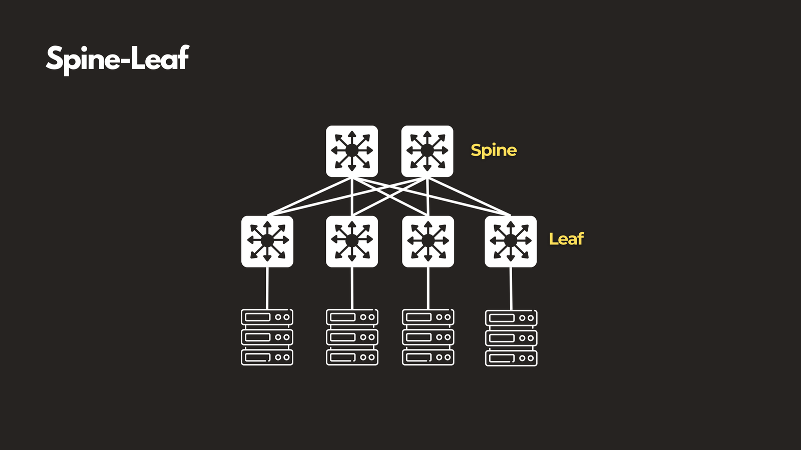
Spine-leaf, also known as CLOS architecture, was. Every leaf switch connects to every spine switch, forming a full mesh between the two layers. The result: any two servers in the data center are always exactly two hops apart, no matter where they physically sit. There’s no distribution layer, and critically, spine switches never connect to each other and leaf switches never connect to each other — all the connectivity logic lives in that leaf-to-spine mesh.
This gives you predictable, low latency and scales horizontally in a very clean way. Need more bandwidth? Add another spine. Need more server ports? Add another leaf.
Spine-leaf is the standard inside AWS, Google, and most modern private data centers — anywhere with heavy server-to-server traffic.
Cloud Network Architecture
Spine-leaf is how cloud providers build their physical infrastructure, but as a customer, you’re working a layer above that — in software, through a cloud console rather than physical switches.
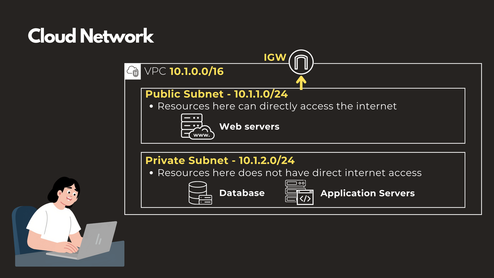
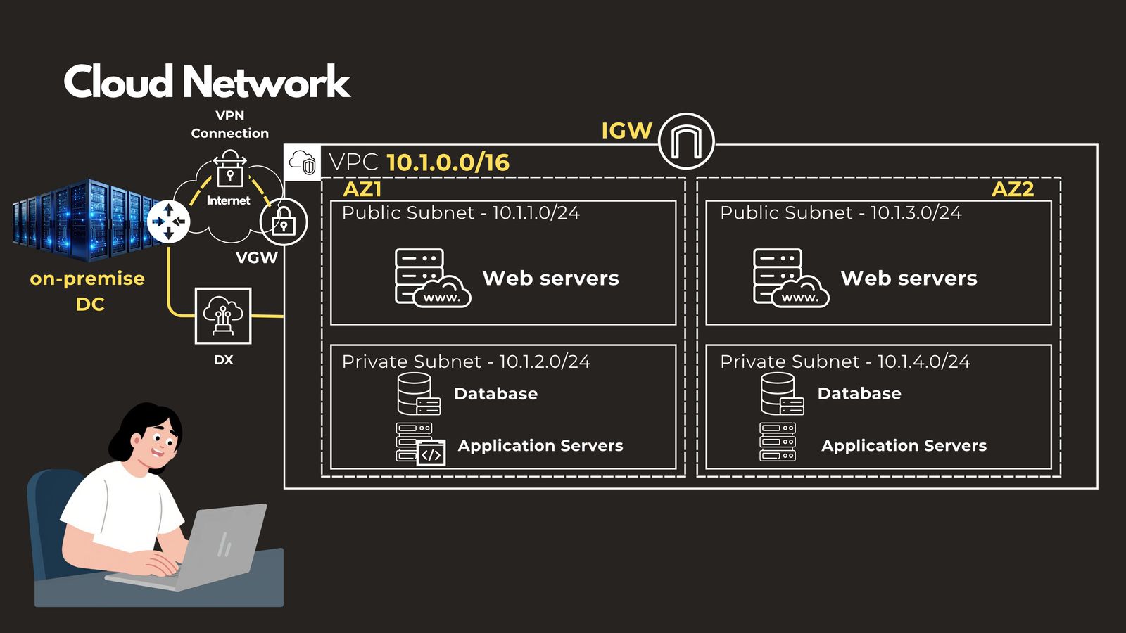
In AWS, Azure, or GCP, you define a virtual network — called a VPC in AWS — and divide it into subnets. Public subnets have a route to an internet gateway and typically host things like load balancers. Private subnets have no direct internet route and are where databases and internal application servers live. Route tables and security groups do the job that VLANs and access control lists do on-premises, just defined as code instead of configured on physical hardware.
For redundancy, cloud architectures spread resources across availability zones — physically separate data centers within the same region — so a single zone failure doesn’t take an application down.
To connect a cloud network back to an on-premises network, you’d typically use a site-to-site VPN or a dedicated private connection like AWS Direct Connect or Azure ExpressRoute. Functionally, that turns the VPC into just another site on your wide area network.
Cloud network architecture applies to any workload running in a public cloud, and increasingly, it’s a piece of nearly every enterprise network in some hybrid form.
WAN Design: Hub-and-Spoke and Mesh
Once you’re connecting multiple physical sites together — branch offices, data centers, cloud VPCs — you’re designing a wide area network (WAN), and there are two fundamental patterns to choose from.
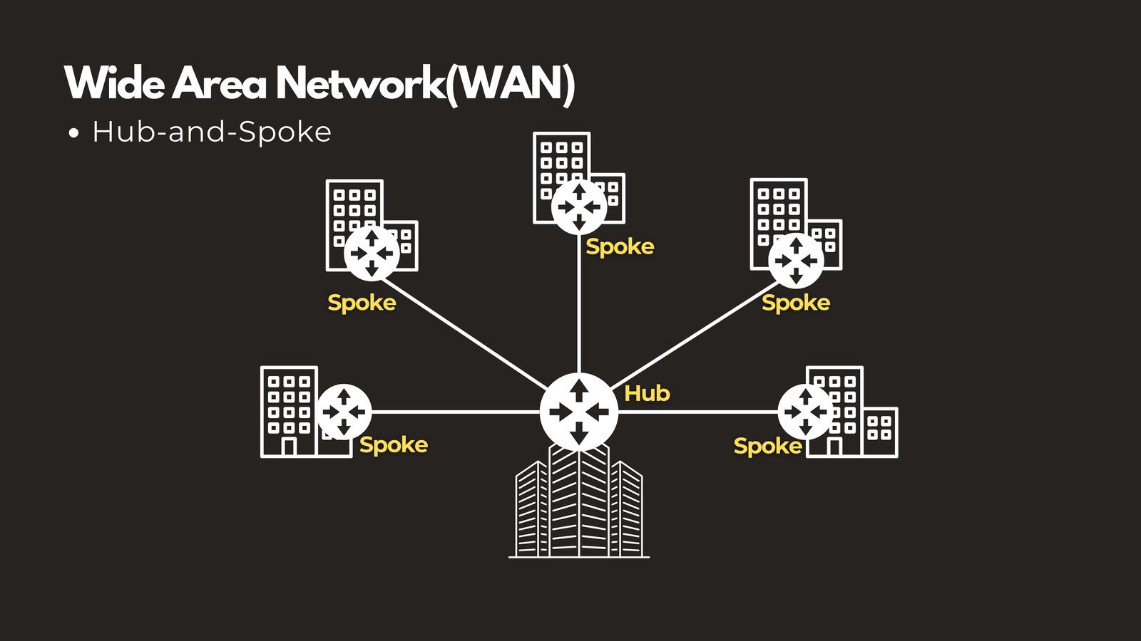
Hub-and-spoke puts one central site, usually a headquarters or primary data center, at the middle of the design, with every branch connecting back to it. It’s simple to deploy and manage, and it’s common with MPLS networks or simpler SD-WAN setups — especially when most traffic really is destined for a central site anyway, like a retail chain where each store mainly talks to corporate systems rather than to other stores. The downside: the hub is both a bottleneck and a single point of failure, and branch-to-branch traffic has to take a longer path than necessary.
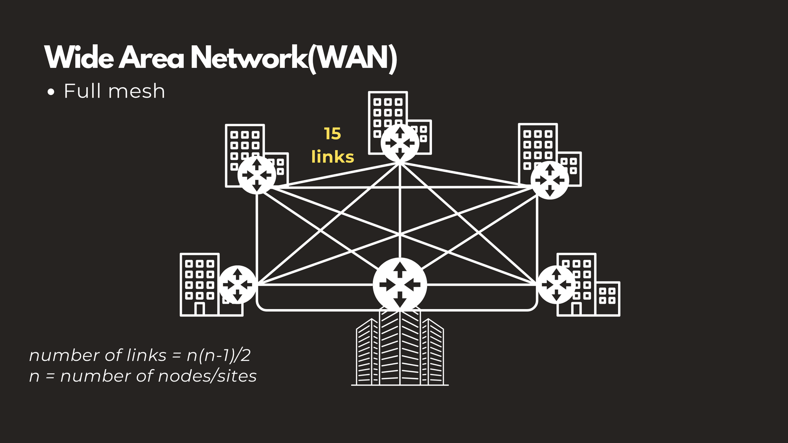
Full mesh takes the opposite approach — every site connects directly to every other site. This gives you the shortest possible path between any two locations and removes the single point of failure. The catch is that the number of connections grows quickly: six sites in full mesh means 15 links to provision and manage, following the formula n(n-1)/2.
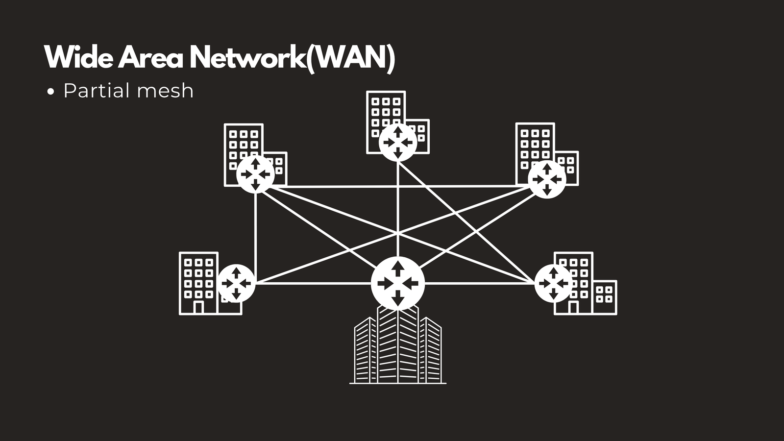
Because full mesh doesn’t scale cleanly, most real-world WANs settle on partial mesh: direct links between the highest-traffic sites, with hub-and-spoke connectivity for everything else. Modern SD-WAN has made this kind of dynamic, partial-mesh design significantly easier to deploy and manage than it used to be under traditional MPLS.
Putting It All Together
None of these architectures is objectively “better” than the others — the right choice depends on your traffic patterns, your budget, and your redundancy requirements.
- Bus and star are the foundational patterns everything else builds on.
- Three-tier or collapsed core covers most enterprise campuses, scaled to size.
- Spine-leaf and cloud VPCs handle data center and cloud workloads built around east-west traffic.
- Hub-and-spoke or partial mesh ties all of those sites together over a WAN.
In practice, most real-world networks are hybrids — a three-tier campus, connected to a spine-leaf data center, connected out to one or more cloud VPCs, all tied together over a partial mesh SD-WAN. Understanding each individual piece is what makes it possible to reason about the whole system when something breaks — or when you’re the one designing it from scratch.
If you found this breakdown useful, check out the full video walkthrough on this link: https://youtu.be/gpxAafGF2V4 where we animate and breakdown each architecture